This project demonstrates how the project Simone works using a matrix keyboard and an RGB LED to emulate the classic game Simon. It uses a finite state machine (FSM) to control the keyboard, an RGB light (RGB LED) to show the intensity, and a button to interact with the system.
This project is intended to be used with the MatrixMCU toolkit. The toolkit is available at GitHub: MatrixMCU.
Click on the image to see the video showing the Simone demo for Nucleo STM32:
You can access the documentation of the project at: Simone Documentation.
Version 1
In Version 1, the system works with the user button only. The user button is connected to the pin PC13. The code uses the EXTI13 interrupt to detect the button press.
| Parameter | Value |
|---|---|
| Pin | PC13 |
| Mode | Input |
| Pull up/ down | No push no pull |
| EXTI | EXTI13 |
| ISR | EXTI15_10_IRQHandler |
| Priority | 1 |
| Subpriority | 0 |
| Debounce time | 100-200 ms |
You can start from the HW dependent part of Version 1.
- Here you can find the project with the basic configuration: Simone Project.
- Here you can find the test files for Version 1: V1 test files
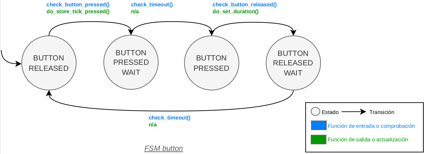
This is the FSM of the button:
Version 2
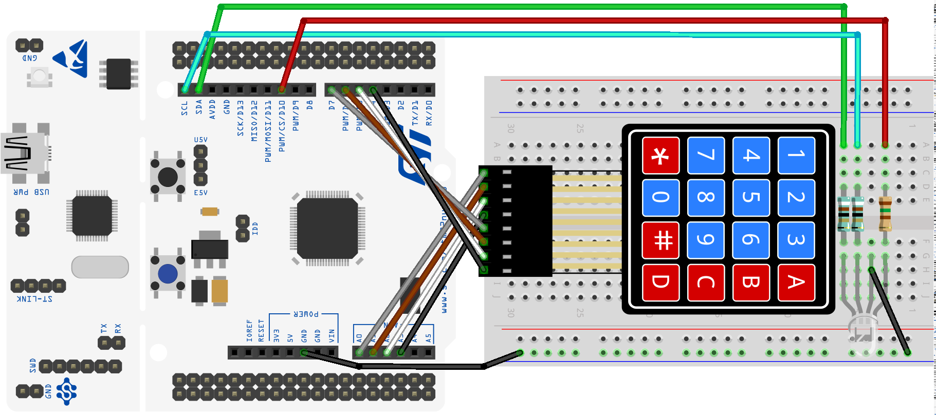
In Version 2, the system adds the keyboard matrix to read the presses of the player in the game.
The connections of the keyboard are shown in the table below:
| Parameter | Value |
|---|---|
| Pin row 1 | PA0 |
| Pin row 2 | PA1 |
| Pin row 3 | PA4 |
| Pin row 4 | PB0 |
| Mode rows | Output |
| Pull up/ down rows | No push, no pull |
| Timeout excitation rows | 25 ms |
| Pin/ EXTI/ ISR column 1 | PA8/ EXTI8/ EXTI9_5_IRQHandler |
| Pin/ EXTI/ ISR column 2 | PB10/ EXTI10/ EXTI15_10_IRQHandler |
| Pin/ EXTI/ ISR column 3 | PB4/ EXTI4/ EXTI4_IRQHandler |
| Pin/ EXTI/ ISR column 4 | PB5/ EXTI5/ EXTI9_5_IRQHandler |
| Mode columns | Input |
| Pull up/ down columns | Pull down |
| Priority all columns | 1 |
| Subpriority all columns | 1 |
| Debounce time all columns | 100-200 ms |
The system uses 1 timer to control the duration of the excitation of each row in the keyboard matrix. The characteristics of this timer are shown in the table below. The FSM will give a value every PORT_KEYBOARDS_TIMEOUT_MS milliseconds.
| Parameter | Value |
|---|---|
| Timer | TIM5 |
| Prescaler | (to be calculated for PORT_KEYBOARDS_TIMEOUT_MS) |
| Period | (to be calculated for PORT_KEYBOARDS_TIMEOUT_MS) |
| ISR | TIM5_IRQHandler() |
| Priority | 2 |
| Subpriority | 0 |
You can start from the HW dependent part of Version 2.
- Here you can find the files needed for the control of the keyboard: Keyboard.
- Here you can find the test files for Version 2: V2 test files
This is the FSM of the keyboard:
Version 3
In Version 3, the system adds the RGB light, which is an RGB LED. The RGB LED is connected to the pins PB6 (red), PB8 (green), and PB9 (blue). The code uses the TIM4 timer to control the frequency of the PWM signal for each color. The RGB LED will show the intensity depending on the difficulty level. The characteristics of the RGB light are shown in the table below.
| Parameter | Value |
|---|---|
| Pin LED red | PB6 |
| Pin LED green | PB8 |
| Pin LED blue | PB9 |
| Mode | Alternative |
| Pull up/ down | No pull |
| Timer | TIM4 |
| Channel LED red | (see the Alternate Function table in the datasheet) |
| Channel LED green | (see the Alternate Function table in the datasheet) |
| Channel LED blue | (see the Alternate Function table in the datasheet) |
| PWM mode | PWM mode 1 |
| Prescaler | (to be calculated for a frequency of 50 Hz) |
| Period | (to be calculated for a frequency of 50 Hz) |
| Duty cycle LED red | (variable, depends on the color to show) |
| Duty cycle LED green | (variable, depends on the color to show) |
| Duty cycle LED blue | (variable, depends on the color to show) |
You have a list full of colors in www.downtownuplighting.com although not all can be shown on an RGB LED.
You can start from the HW dependent part of Version 3.
- Here you can find the files needed for the control of the RGB light: RGB light.
- Here you can find the test files for Version 3: V3 test files
This is the FSM of the RGB light:
Version 4
In Version 4 the system completes its FSM to interact with the user button, the keyboard, and the RGB light. The system will work as a game where the player has to repeat a sequence of colors shown by the RGB light by pressing the corresponding keys on the keyboard. The system will increase the length of the sequence with each successful round, and it will provide visual feedback through the RGB light for correct and incorrect inputs.
There are no files documented for the FSM of Version 4, and you have to create them from scratch following the laboratory notebook. You can use the files of the previous versions as a reference.
Check the HW dependent part of Version 4.
YOU MUST DRAW THE FSM OF THE SYSTEM BY YOURSELF AND PUT IT HERE.

Version 5
In Version 5 the user adds its own functions to the system. Check the manual of the system to know how to add your own functions.
Getting Started
Download this project and place it in the projects folder of the MatrixMCU toolkit.
Prerequisites
Be sure that you fulfill the prerequisites of the MatrixMCU toolkit and it is up to date.
Document your code
Watch this video to better understand how to document your code with Doxygen:

Authors
- Josué Pagán - email: j.pagan@upm.es
License
This project is licensed under the MIT License - see the LICENSE file for details.
Acknowledgments
Acknowledgments to all professors of the SDG2 subject.
In memory of Mario Garrido Gálvez (1981-2025), a great professor and colleague. RIP.
References
- [1]: Documentation available in the Moodle of the course
- [2]: Embedded Systems with ARM Cortex-M Microcontrollers in Assembly Language and C (Fourth Edition) for explanations and examples of use of the ARM Cortex-M microcontrollers in C with CMSIS.
- [3]: Programming with STM32: Getting Started with the Nucleo Board and C/C++ for examples of use of the STM32 microcontrollers with the HAL of ST.
- [4]: The C Programming Language
- [5]: Aspectos prácticos de diseño y medida en Laboratorios de Electrónica for the use of the oscilloscope and the function generator.
- [6]: Nucleo Boards Programming with th STM32CubeIDE for examples of use of the STM32 microcontrollers with the STM32CubeIDE.