This project demonstrates how the project Urbanite works using an ultrasound transceiver to measure the distance to an object in a parking aid system mounted on a car. It uses a finite state machine (FSM) to control the ultrasound sensor, a display (RGB LED) to show the distance, and a button to interact with the system.
This project is intended to be used with the MatrixMCU toolkit. The toolkit is available at GitHub: MatrixMCU.
Click on the image to see the video showing the Urbanite demo for Nucleo STM32:
Version 1
In Version 1, the system works with the user button only. The user button is connected to the pin PC13. The code uses the EXTI13 interrupt to detect the button press.
| Parameter | Value |
|---|---|
| Pin | PC13 |
| Mode | Input |
| Pull up/ down | No push no pull |
| EXTI | EXTI13 |
| ISR | EXTI15_10_IRQHandler |
| Priority | 1 |
| Subpriority | 0 |
| Debounce time | 100-200 ms |
You can start from the HW dependent part of Version 1.
- Here you can find the project with the basic configuration: Urbanite Project.
- Here you can find the test files for Version 1: V1 test files
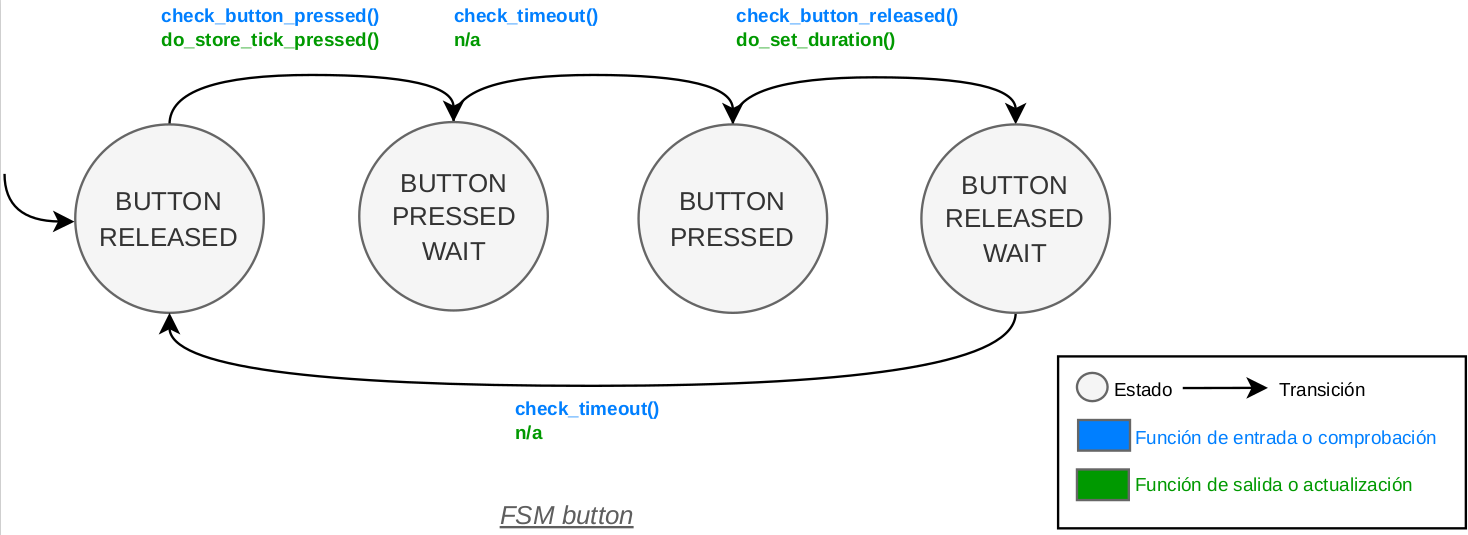
This is the FSM of the button:
Version 2
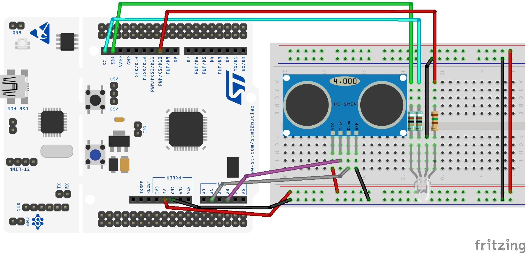
In Version 2, the system adds the ultrasonic transceiver to measure the distance to an object. The trigger pin is connected to the pin PB0, and the echo pin is connected to the pin PA1. The code uses the TIM2, TIM3 and TIM5 timers to control the ultrasonic transceiver.
To measure the distance in centimeters with a timer resolution of 1 microseconds, we can say that 1 cm is equivalent to 58.3 microseconds. The speed of sound is 343 m/s at 20ºC. The ultrasonic transceiver is the HC-SR04.
The characteristics and connections of the ultrasonic transceiver HC-SR04 are shown in the table below:
| Parameter | Value |
|---|---|
| Power supply | 5 V |
| Current | 15 mA |
| Angle of aperture | 15º |
| Frequency | 40 kHz |
| Measurement range | 2 cm to 400 cm |
| Pins | PB0 (Trigger) and PA1 (Echo) |
| Mode | Output (Trigger) and alternative (Echo) |
| Pull up/ down | No pull |
| Timer | TIM3 (Trigger) and TIM2 (Echo) |
| Channel | (see the Alternate Function table in the datasheet) |
The system uses 3 timers: (i) one to control the duration of the trigger signal, (ii) another to measure the echo time, and (iii) another to measure the timeout between consecutive measurements that we want to make. The timing diagram of the measurements is shown in the figure below.
To generate the trigger signal, we will activate (1 logical) the trigger pin for at least 10 microseconds. To control the duration of this signal, we will configure the timer TIM3 as shown in the table below.
| Parameter | Value |
|---|---|
| Timer | TIM3 |
| Prescaler | (to be calculated for PORT_PARKING_SENSOR_TRIGGER_UP_US) |
| Period | (to be calculated for PORT_PARKING_SENSOR_TRIGGER_UP_US) |
| ISR | TIM3_IRQHandler() |
| Priority | 4 |
| Subpriority | 0 |
To measure the echo time, we will configure the timer TIM2 in input capture mode, which will capture the value of the counter at the moment the echo signal is activated and deactivated.
| Parameter | Value |
|---|---|
| Timer | TIM2 |
| Prescaler | (to be calculated for 1 microseconds) |
| Period | (to be calculated for 1 microseconds) |
| ISR | TIM2_IRQHandler() |
| Priority | 3 |
| Subpriority | 0 |
The timer that controls the timeout between consecutive measurements is TIM5. The characteristics of this timer are shown in the table below. The FSM will give a value every PORT_PARKING_SENSOR_TIMEOUT_MS milliseconds.
| Parameter | Value |
|---|---|
| Timer | TIM5 |
| Prescaler | (to be calculated for PORT_PARKING_SENSOR_TIMEOUT_MS) |
| Period | (to be calculated for PORT_PARKING_SENSOR_TIMEOUT_MS) |
| ISR | TIM5_IRQHandler() |
| Priority | 5 |
| Subpriority | 0 |
You can start from the HW dependent part of Version 2.
- Here you can find the files needed for the control of the ultrasonic transceiver: Ultrasonic Transceiver.
- Here you can find the test files for Version 2: V2 test files
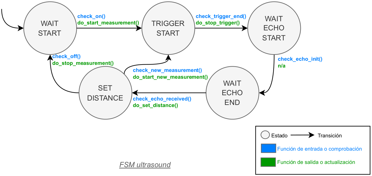
This is the FSM of the ultrasonic transceiver:
Version 3
In Version 3, the system adds the display, which is an RGB LED. The RGB LED is connected to the pins PB6 (red), PB8 (green), and PB9 (blue). The code uses the TIM4 timer to control the frequency of the PWM signal for each color. The RGB LED will show the distance to the object detected. The characteristics of the display are shown in the table below.
| Parameter | Value |
|---|---|
| Pin LED red | PB6 |
| Pin LED green | PB8 |
| Pin LED blue | PB9 |
| Mode | Alternative |
| Pull up/ down | No pull |
| Timer | TIM4 |
| Channel LED red | (see the Alternate Function table in the datasheet) |
| Channel LED green | (see the Alternate Function table in the datasheet) |
| Channel LED blue | (see the Alternate Function table in the datasheet) |
| PWM mode | PWM mode 1 |
| Prescaler | (to be calculated for a frequency of 50 Hz) |
| Period | (to be calculated for a frequency of 50 Hz) |
| Duty cycle LED red | (variable, depends on the color to show) |
| Duty cycle LED green | (variable, depends on the color to show) |
| Duty cycle LED blue | (variable, depends on the color to show) |
You have a list full of colors in www.downtownuplighting.com although not all can be shown on an RGB LED.
The following table shows the duty cycle values for each color in function of the distance. Be careful, these values are not the ones that you put in the **CCRx register!** They depend on the PORT_DISPLAY_RGB_MAX_VALUE. The values are shown in the table below.
| Distance | Color | LED red | LED green | LED blue |
|---|---|---|---|---|
| $[0-25]$ cm | Red (danger) | 100% | 0% | 0% |
| $(25-50]$ cm | Yellow (warning) | 37% | 37% | 0% |
| $(50-150]$ cm | Green (no~problem) | 0% | 100% | 0% |
| $(150-175]$ cm | Turquoise (info) | 10% | 35% | 32% |
| $(175-200]$ cm | Blue (OK) | 0% | 0% | 100% |
| Other distances | Off (inactive) | 0% | 0% | 0% |
You can start from the HW dependent part of Version 3.
- Here you can find the files needed for the control of the display: Display.
- Here you can find the test files for Version 3: V3 test files
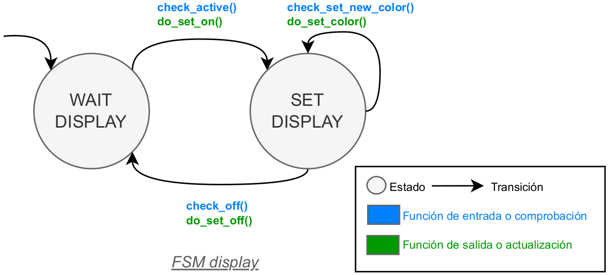
This is the FSM of the display:
Version 4
In Version 4 the system completes its FSM to interact with the user button, the ultrasonic transceiver, and the display. The system will show the distance to the object detected in the display.
There are no files for Version 4, and you have to create them from scratch. You can use the files of the previous versions as a reference.
Check the HW dependent part of Version 4.
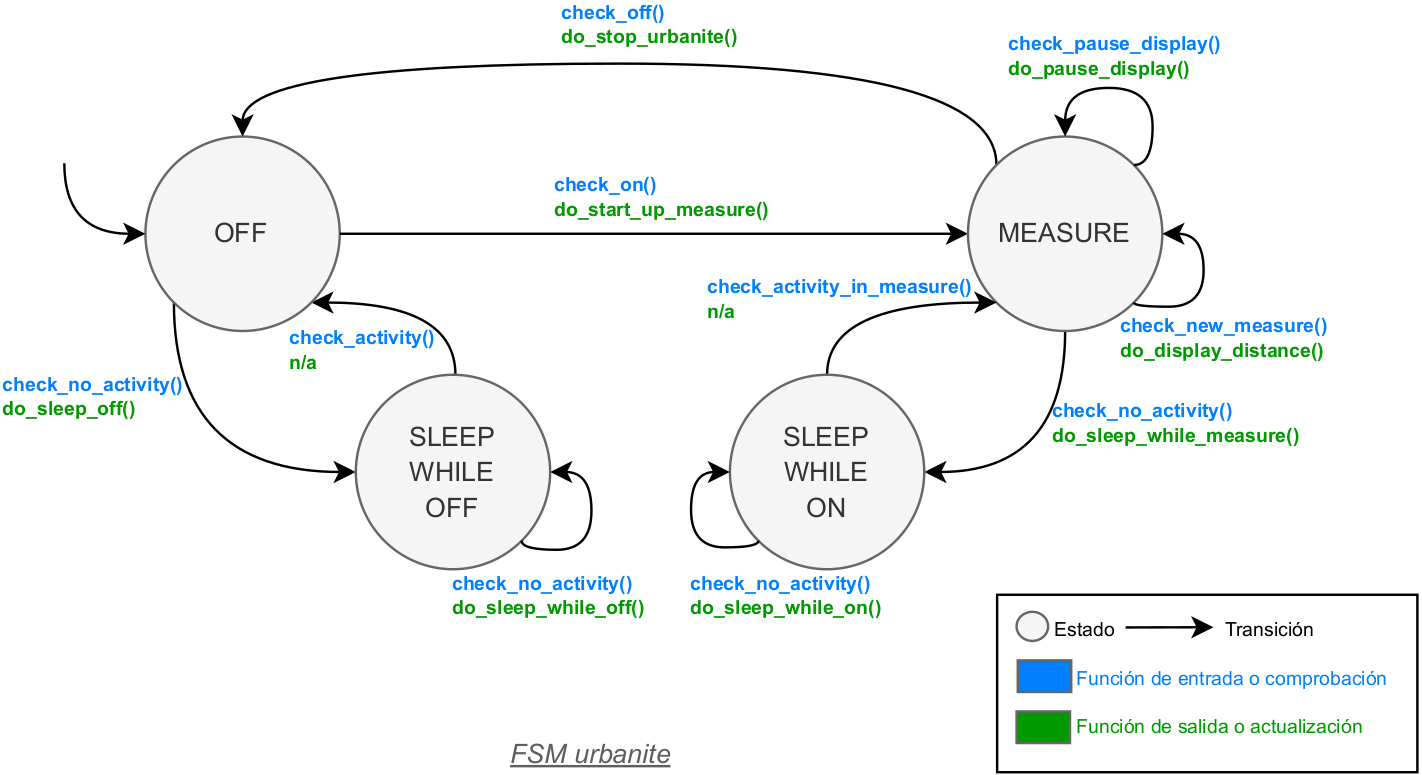
This is the FSM of the system:
Version 5
In Version 5 the user adds its own functions to the system. Check the manual of the system to know how to add your own functions.
Getting Started
Download this project and place it in the projects folder of the MatrixMCU toolkit.
Prerequisites
Be sure that you fulfill the prerequisites of the MatrixMCU toolkit and it is up to date.
Document your code
Watch this video to better understand how to document your code with Doxygen:

Authors
- Josué Pagán - email: j.pagan@upm.es
- Román Cárdenas - email: r.cardenas@upm.es
License
This project is licensed under the MIT License - see the LICENSE file for details.
Acknowledgments
- Iván Ferández Martín, Sergio Esteban Romero, and all professors of the SDG2 subject.
References
- [1]: Documentation available in the Moodle of the course
- [2]: Embedded Systems with ARM Cortex-M Microcontrollers in Assembly Language and C (Fourth Edition) for explanations and examples of use of the ARM Cortex-M microcontrollers in C with CMSIS.
- [3]: Programming with STM32: Getting Started with the Nucleo Board and C/C++ for examples of use of the STM32 microcontrollers with the HAL of ST.
- [4]: The C Programming Language
- [5]: Aspectos prácticos de diseño y medida en Laboratorios de Electrónica for the use of the oscilloscope and the function generator.
- [6]: Nucleo Boards Programming with th STM32CubeIDE for examples of use of the STM32 microcontrollers with the STM32CubeIDE.