Portable functions to interact with the display system FSM library. All portable functions must be implemented in this file. More...
#include <stdio.h>#include "port_display.h"#include "port_system.h"#include "stm32f4_system.h"#include "stm32f4_display.h"Data Structures | |
| struct | stm32f4_display_hw_t |
| Structure to define the HW dependencies of an RGB LED. More... | |
Functions | |
| stm32f4_display_hw_t * | _stm32f4_display_get (uint32_t display_id) |
| Get the display struct with the given ID. More... | |
| void | _timer_pwm_config (uint32_t display_id) |
| Configure the timer that controls the PWM of each one of the RGB LEDs of the display system. More... | |
| void | port_display_init (uint32_t display_id) |
| Configure the HW specifications of a given display. More... | |
| void | port_display_set_rgb (uint32_t display_id, rgb_color_t color) |
| Set the Capture/Compare register values for each channel of the RGB LED given a color. More... | |
Variables | |
| static stm32f4_display_hw_t | displays_arr [] |
| Array of elements that represents the HW characteristics of the RGB LED of the display systems connected to the STM32F4 platform. More... | |
Detailed Description
Portable functions to interact with the display system FSM library. All portable functions must be implemented in this file.
- Date
- 2025-01-01
Function Documentation
◆ _stm32f4_display_get()
| stm32f4_display_hw_t* _stm32f4_display_get | ( | uint32_t | display_id | ) |
Get the display struct with the given ID.
- Parameters
-
display_id Button ID.
- Returns
- Pointer to the display struct.
- NULL If the display ID is not valid.
◆ _timer_pwm_config()
| void _timer_pwm_config | ( | uint32_t | display_id | ) |
Configure the timer that controls the PWM of each one of the RGB LEDs of the display system.
This function is called by the port_display_init() public function to configure the timer that controls the PWM of the RGB LEDs of the display.
- Warning
- The timer is common for all the RGB LEDs of one RGB display despite each one has its own channel. If you introduce more RGB displays, you must configure a new timer for each one. Because of this, you **must encapsulate the configuration of the timer in a
switchorifstatement.*
- Note
- This function does not set the duty cycle of the PWM signal. This is done in the
port_display_set_rgb()function where the color is set.
TODO alumnos:
PWM timer setup
✅ 1. Enable the clock source of the timer
💡 To know if the source clock isAPB1orAPB2, check the clock tree in the user manual (Figure 3. STM32F446xC/E block diagram)
✅ 2. Disable the counter (registerCR1) and enable the autoreload preaload (bitARPE) ✅ 3. Reset the counter (registerCNT), set the autoreload value (registerARR) and the prescaler (registerPSC) for a frequency of 50 Hz.
PWM mode configuration
- Note
- Check table "Table 11. Alternate function" in the datasheet to select the channel more alternate functions.
✅ 5. Disable the output compare (register
CCER) for each one of the corresponding channels. Take into account the channel number (1, 2, 3, or 4) and the channel enable bit (CCxE)
✅ 6. Clear the P and NP bits (CCxP and CCxNP) of the output compare register (CCER) for each one of the corresponding channels .
✅ 7. Set both (i) mode PWM 1, and (ii) enable preload (register CCMRx) for each one of the corresponding channels.
💡 To set the mode PWM tomode 1you must set the bitsOCxMin theCCMRxregister to the corresponding values according to the explanations of the manufacturer. You can find it in the explanations for the TIMx_CCMRx register for timers TIM2-TIM5 in Sections 17.4.7 and 17.4.8 in the reference manual
💡 To enable the preload you must set the bitOCxPEto1in the same register. ✅ 8. Generate an update event (registerEGR) by setting theUGbit. This will load the values of theARRandPSCregisters into the active registers.
- Parameters
-
display_id Display system identifier number.
◆ port_display_init()
| void port_display_init | ( | uint32_t | display_id | ) |
Configure the HW specifications of a given display.
Assuming we are using an STM32F4-based platform, this function must call the following functions:
TODO alumnos:
✅ 1. Retrieve the display configuration struct calling
_stm32f4_display_get().
✅ 2. Call functionstm32f4_system_gpio_config()with the right arguments to configure each RGB LED as in alternate mode and no pull up neither pull down connection.
✅ 3. Call functionstm32f4_system_gpio_config_alternate()with the right arguments to configure the alternate function of the each RGB LED.
✅ 4. Call function_timer_pwm_config()to configure the timer and the PWM signal of the display.
✅ 5. Call functionport_display_set_rgb()to set the RGB LED to off.
- Parameters
-
display_id Display ID. This index is used to select the element of the displays_arr[]array
◆ port_display_set_rgb()
| void port_display_set_rgb | ( | uint32_t | display_id, |
| rgb_color_t | color | ||
| ) |
Set the Capture/Compare register values for each channel of the RGB LED given a color.
This function disables the timer associated to the RGB LEDs, sets the Capture/Compare register values for each channel of the RGB LED, and enables the timer.
- Warning
- This function is valid for any given RGB LED, however, each RGB LED has its own timer. Write the code in a conditional statement to check the display_id.
TODO alumnos:
✅ 1. Retrieve the individual RGB values from the
colorparameter and follow the flowchart to set the RGB LED color by configuring the PWM signals appropriately: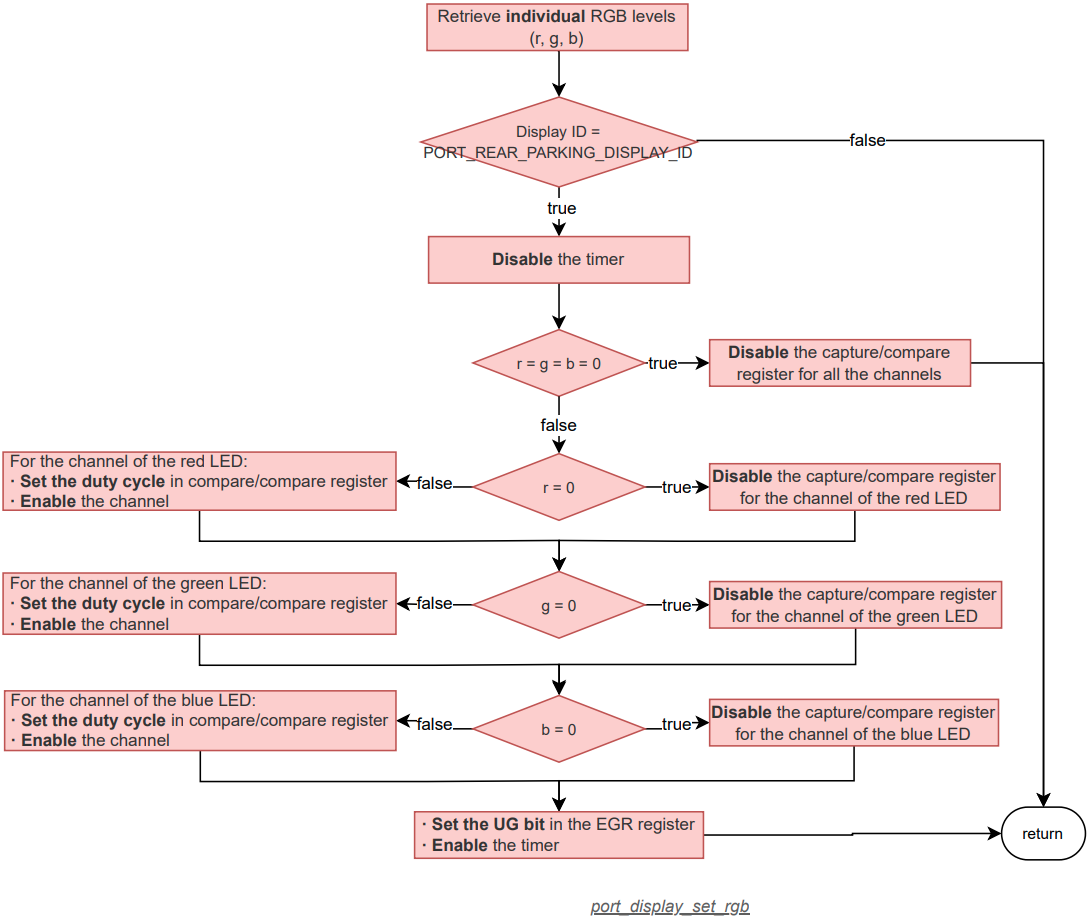
- Parameters
-
display_id Display system identifier number. color RGB color to set.
Variable Documentation
◆ displays_arr
|
static |
Array of elements that represents the HW characteristics of the RGB LED of the display systems connected to the STM32F4 platform.
This must be hidden from the user, so it is declared as static. To access the elements of this array, use the function _stm32f4_display_get().